Projection
A map projection is a method for taking the curved surface of the Earth (3D) and displaying it on a flat surface (2D). A projected coordinate system is always based on a geographic coordinate system. The below table shows a few key differences between a GCS and PCS.
| GCS (Geographic Coordinate System) | PCS (Projected Coordinate System) |
| 3D Spheroid Surface | 2D Flat Surface |
| Latitude and Longitude | XY Locations |
| Datum | Map Projection |
Map projections are designed for specific purposes. Conformal projections preserve the shape of the features, Equal area projections preserve the area of the feature displayed, Equidistant projections preserve the distance between certain features on a map while the Azimuthal projection maintains the directions of all points on the map.
Common Errors Due to Incorrectly set Coordinate Systems

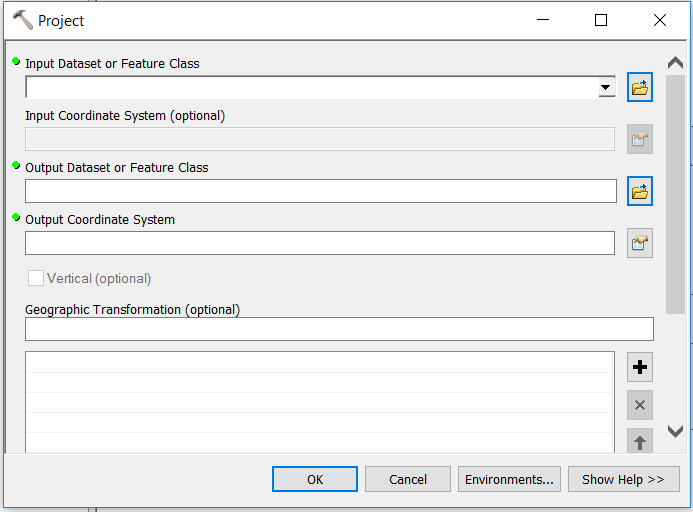
Quick Easy Steps for Projecting
- Enquire with the source owner of the data, research or decide which coordinate system the data should be assigned. If the original coordinate system of the data cannot be sourced, it will be your responsibility to assign the correct coordinate system to the data.
- Before deciding which coordinate system the data should be assigned; visually assess the data or the layer properties of the data, to check whether the data is originally in GCS (Geographic Coordinate System) or PCS (Projected Coordinate System). Add the data in the Map Window in ArcMap.
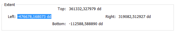
Take note of the Extent that has large numbers 361332,327979dd. This indicates that this is a Projected Coordinate System.
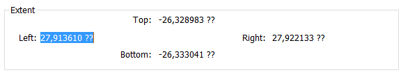
Notice the Extent has small numbers -26,333041?? starting with to decimals. This indicates that they are Decimal Degree measurement which is a Geographic Coordinate System
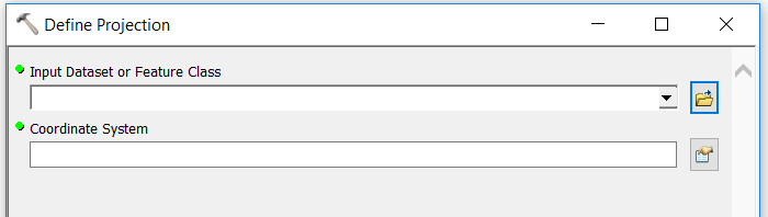
- Define the coordinate of your data by using the Define Projection tool (This tool is for datasets that have an unknown or undefined coordinate system defined)
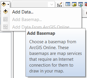
- After defining the coordinate system of the data, check against a Basemap if it is located at the correct place.
- Project the data using the Projection Tool (This tool is to change the dataset from one coordinate system to another)
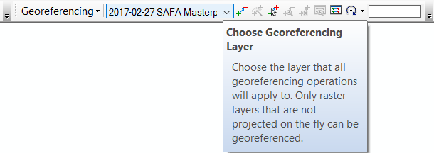
Georeferencing and Spatial Adjustment
Georeferencing
Provides a correct, real-world spatial reference to Raster or CAD datasets; which is either missing a real-world spatial reference or has an unknown spatial reference.
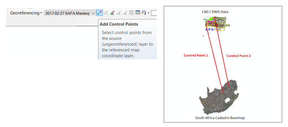
Georeferencing is the process of aligning geographic data to a reference dataset in a known coordinate system. This method helps to associate a physical map, raster or CAD document with a spatial location. When you Georeferencing a dataset, you define where the data is located using map coordinates. Georeferencing uses Control Points, that associates the data with a specific location on earth; which allow the georeferenced dataset to be viewed, queried and analysed with other geographic data.
During Georeferencing it is important to use correct Reference Datasets; raster or vector feature classes can be used as reference data only if the data has the correct spatial reference. Identify distinctive locations that are visible in both datasets, these will be used as Control Points. The control points link the original dataset that is being georeferenced to the reference data – the first control point is plotted on the original dataset (data that needs to be aligned with the reference data) the second control point is then plotted on the corresponding location on the reference data. Corresponding Links are established from the control points, which will be used to align the original dataset with the reference data.
Spatial Adjustment
Like Georeferencing; Spatial Adjustment aligns the original dataset to a reference data, based on links between corresponding control points. The major difference between the two methods is the original datasets and the usage of the method; Georeferencing is used to re-create a missing or unknown spatial reference for Raster or CAD data while Spatial Adjustment is used to correct the alignment of editable vector data.
Data in GIS usually comes from different sources, which means the user is required to perform additional work to integrate and use the data together. Spatial adjustment is used to correct; inconsistencies between data sources, correct geometric distortions and align features together. There are a variety of adjustment methods that can be used to adjust all editable data sources. Another interesting task in spatial adjustment is the ability to transfer attributes from one feature to another.
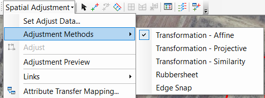
There are three methods for performing spatial adjustment: transformation, edgematching and rubber sheeting. The edgematching method is typically used for connecting the end points of features with each other, rubber sheeting is best used for aligning minor geometric adjustments; this method stretches, shrinks and reorients features to match the reference data and the transformation method is like the transformation method used in georeferencing; it will shift, scale, rotate and skew the data if necessary.
The table below shows the major differences between the two methods above.
| Georeferencing | Spatial Adjustment |
| The process of aligning data with missing or unknown spatial reference to reference data in a known coordinate system | Editing functionality for aligning data with a spatially accurate reference dataset |
| Transformation Method | Transformation Method Edgematching Method Rubber Sheeting Method |
| Works Out of the Edit session | Works in the Edit Session |
| CAD, Raster Imagery, Aerial Imagery | Feature Class or Shapefile (editable vector data) |
Common Errors Due to Inconsistency in Data
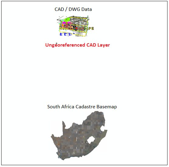
Error showing an un-georeferenced CAD Layer
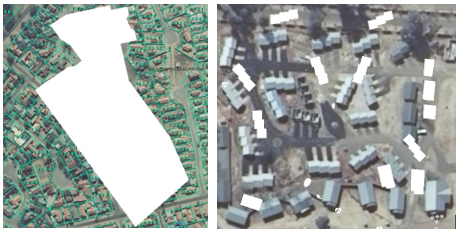
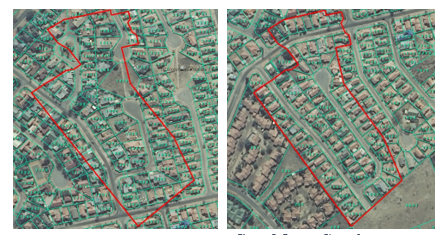
Errors showing Features Classes (vector data) that do not align to the Reference Data
Quick Easy Steps for Correctly Aligning CAD/DWG Data
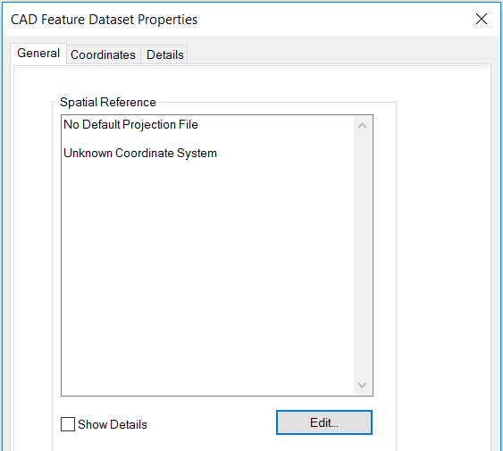
- Assign GCS (Geographic Coordinate System) to the CAD/DWG file (WGS_1984) in ArcCatalog, if it has no spatial coordinate system / unknown coordinate system.
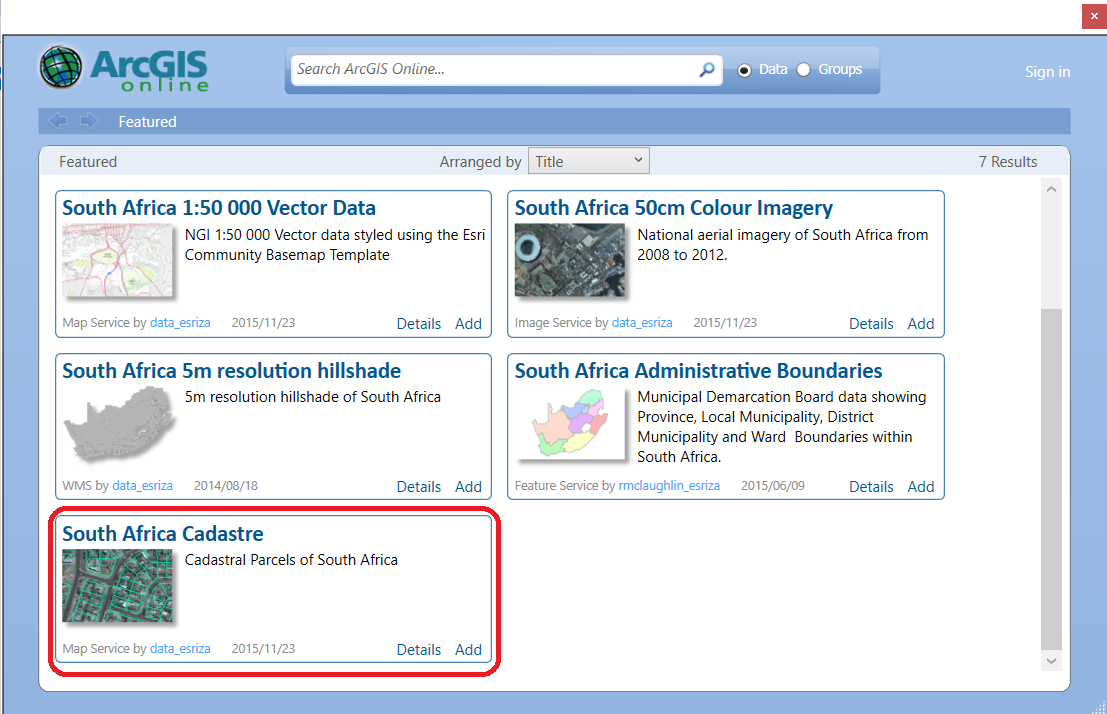
- Load a Basemap for reference purposes, it is advisable to choose the South Africa Cadastre Basemap available on ArcGIS Online Basemap especially if you are using CAD/DWG Files.
- Georeference the CAD/DWG file, using the reference data (data in the correct geographic location that has the correct Spatial Reference i.e. farm portions).
- When Georeferencing; it is vital to have two distinctive locations in both the CAD/DWG File and the Reference Data, these two distinctive locations will be used as Control Points.
- Export the georeferenced CAD Feature to a Feature Class place it in a file geodatabase once georeferenced, first create a new file geodatabase if necessary. Working with Feature Classes is recommended especially if you must spatially adjust the data after Georeferencing.
- Adjust the feature class by using Spatial Adjustment (use the Affine method)
- Use the Define Projection tool to define a coordinate for the feature class that perfectly aligns with the Reference data.
- Project, it accordingly and assess the results
Limitations of Georeferencing CAD datasets
Georeferencing a CAD dataset is limited to one- and two-point transformations using the similarity transformation method:
- one-point transformation comprises one link and moves the dataset
- two-point transformation comprises two links and moves, rotates, and scales the dataset uniformly
Both methods preserve the shape and angles of the CAD dataset, however, the aspect ratio (the ratio of the width to the height of an image or screen) of the CAD drawing is distorted
Spatial Adjustment of CAD datasets
The spatial adjustment method maintains the aspect ratio of the CAD drawing and prevents skewing to the x- and y- axes. However, it should be noted there will be an inherent deformation of the aspect ratio, from the georeferencing step.
Contributor: Busisiwe Ngobe